The purpose of this project is to develop the inverter for experiments in the field of asynchronous machine control. So the main goal is not only implementat the FOC control, but also make easly programmeble and algorithm customizable hardware platform.
For the desire to simplify the coding, it was decided to use MATLAB Embedded Coder to generate code in C language for model Simulink.
Vector control is implemented by the classical scheme in the model EmbeddedFOC.mdl

Model inputs are:
– theta – is the angular position of the rotor (electrical angle)
– enable – if enable = 1, the vector control is activated when enable = 0 – then the scalar
– I_a, I_b – are currents of motor supply phases A and B from the current sensors (in Amps)
– scalar_freq – is the voltage frequency for the scalar mode (Hz)
– omega_ref – the speed setpoint for vector mode (in rad / sec)
– i_sd_ref – is the setpoint of magnetization current for vector mode (in Amps)
– scalar_ampl – is the amplitude of the output voltage for the scalar mode (normalized value between 0 and 1)
Model outputs:
– u_abc – are output voltage for motor leg phases A, B, C (a normalized value between -1 and 1)
– i_s_dq – are stator currents in synchronous rotating coordinate system (in A)
– slip – is the slip velocity
– debug – is the port for debug signals
The central part if model is a subsystem FOC

it implements the field-oriented control of stator currents in the rotating reference frame. Actually subsystem consists of three PI controllers: stabilizer of magnetizing current 


To verify the algorithm in EmbeddedFOC.mdl two models were created:
– Pure_SimPowSys_model_scalar.mdl – motor control in scalar mode,
– Pure_SimPowSys_model_vector.mdl – management in vector mode.
Some characteristics of implementation:
– One-step integration scheme (ode1) was selected,
– Model discretization period – 1 ms,
– Floating-point arithmetic with single-precision (float)
– The real execution time for one cycle of the algorithm in the order of 150 us
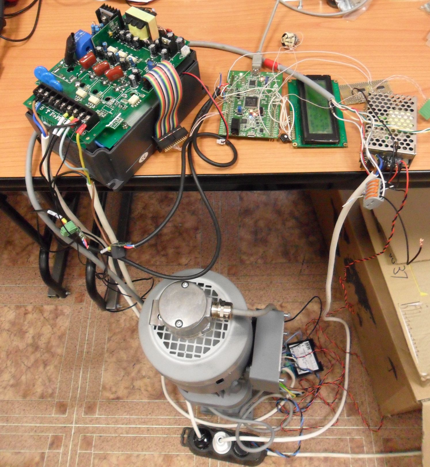
As the hardware platform board STM32F4DISCOVERY has been used. It based on the STM32F407VGT6 processor which allows to implement complex numerical algorithms and contains all the necessary peripherals. Parts of code to generate PWM signals and read incremental encoder taken from the STM32 FOC firwmare libraries v2.0.
Connection to microcontroller:

Variable resistor connected to pin PC1 for the speed setpoint manipulation. Button “User” on the board turn on the vector control mode (initially after power on it works in scalar mode).
For the power stage China-made inverter was used. It consists of the control board and power stage board, connected via ribbon planar cable. STM32F4DISCOVERY board was connected instead of the standard control board.
As the current sensors Allegro ACS712 with rated current 5A are used.
Check-list to customize the implementation for a specific hardware:
1. Set parameters POLE_PAIR_NUM (number of motor poles) and ENCODER_PPR (encoder points per one revolution) in the file stm32f10x_encoder.c
2. Adjust parameter I_MAX. This is a current, which corresponds to maximum current from current sensor in case of ADC full-scale reading (file main.c)
3. You can edit the definition of the variable TimerPeriod to adjust the PWM frequency (5 kHz by defualit) – the file main.c
4. In the subsystem Observer [omega_slip] (model EmbeddedFOC.mdl), in the text of embedded MATLAB-functions edit the time constant of the motor (tau_r). For this the values of the total inductance of the rotor (magnetizing inductance + stray inductance) and the rotor resistance are needed.
5. In the subsystem FOC (model EmbeddedFOC.mdl) edit the parameters of all PI controllers: PID Controller [flux], PID Controller [torque], PID Controller [speed].
6. Generate code for EmbeddedFOC.mdl (press Ctrl + B) from Simulink models
7. Move files EmbeddedFOC.c, EmbeddedFOC.h, EmbeddedFOC_data.c, EmbeddedFOC_private.h. EmbeddedFOC_types.h from folder EmbeddedFOC_ert_rtw (where it is created is EmbeddedFOC.mdl) to a folder Matlab in the source project folder Keil uVision
It is important to notice that the generated code is modified as follows: in a file line rtwtypes.h
typedef double real_T;
replaced by
typedef float real_T;
for using floating-point single precision, because STM32F4 natively supports only single precision
For bring it to working state the following sequence is recommended:
1. Start the motor in scalar mode (enable = 0).
2. Inside STM32 you can output signals to two DACs for debug purpose. Try to output the measured phase currents to DAC to verify that the current sensors are working properly and the ADC is really measure signals.
3. Next output to the DAC currents in the rotating frame 
4. Verify that the mechanical speed calculated form the encoder signals is greater then zero.
5. Turn off the power stage and try to rotate motor shaft manually to verify that the correct angular position is measured by encoder.
6. Disconnect the output of PID Controller [speed] in the model and use constant setpoint of
7. Verify stabilization of current
8. Connects back the output of PID Controller [speed], tune its coefficients if necessary.
Proposed implementation was tested the gearmotor SEW-Eurodrive DT71C4
Download:
– Simulink models,
– Project files (Keil uVision)

Thank you
U are wellcome.
btw i still working from time to time on this project. hope will post some updates in future. especially simple power stage design and PCB
With the PCB will be perfect.
Please check this out https://akpc806a.wordpress.com/2015/01/18/fsbb30ch60-evaluation-board/
Hello Sir,
I am Akash Prajapati from india and currently working on stm32 for my dissertation topic.
I am working on induction motor control and I required DTC method program.If you have done work on DTC so its my humble request to you that plz sir help me.
Your Faithfully
akash
Hi!
Sorry, never do DTC. Have some doubts is it really possible to implement using MCU like STM32.
In your case I would like recommend to look to FPGA as well. Here is nice new chip which is FPGA with ADC, and very cheap board
http://www.altera.com/products/devkits/altera/kit-max-10-evaluation.html
Hello sir,
Can you give me program of 120 degree phase shift PWM of 50hz for the induction motor run of stm32f407vg.
The project that posted here is just what you need.
You have to connect the PC1 to +3,3V and it should produce 50Hz PWM outputs
Actually I want 6 outputs of PWM. Among them 3 pwms are complementary of other three waveforms and also the main three waveforms are 120 degree phase shift apart.
Signals at pin PE9 to PE12 are what you really need. This is SVPWM along with complementary outputs shifted by 120 deg (as in 3 phase AC system)
This program shows 0 error but it is not loading on my STM32F407VG kit. It shows like stm.dll file missing
When I try to load your Program on my STM32F407VG Discovery Card it shows the error like” Unknown Device Connected”. Plz Give me the Solution. I am Connecting my Card with USB cabble to PC.
Hello
Can you upload the IOC file of stm32f4 because it shows the problem like parameters not configured etc.
Hi,
just uploaded it here
http://sites.google.com/site/akpc806a/SimpleGPIO.ioc?attredirects=0&d=1
where did you get the problems? in matlab? make sure, that you opened all properties of GPIO and set correct pins
After I configured the stm32 mcu block than when i insert other blocks than i got the problem of configuration of other blocks like timer,GPIO etc.
Plz reply me
Hello sir,
When I tried to load this project on my STM32f407vg card it shows error like ” Unknown device connect” so how this error can removed?
Can you load different firmware project to your board?
Are project settings set up correct for your board (ST-Link settings, JTAG/SWD, etc)
Ya i have installed the ST link Utility V2. and I also have run some code on kit. If required which kind of settings should be there?
Which kind of setting are required to load program on the kit? I am using ST link Utility V2.
Please, set all the configuration of Debugger and Flash download tool exactly the same as for projects which you are able to run. Important are SWD/Jtag settings and clock speed, reset options
I have configured all the settings but still it show the message like”Unknown device is connected” Plz send me the settings
i program my stm32 board but my PE9 to PE12 pwm is not 120 degrees and all them are same when i check what can i do for 120 degrees between U,V,W phases thanks
Hello sir is it possible to have also forward and reverse option in this code?
thank you